High Voltage / Piezo Amplifiers & Signal Conditioners
Fiber Optic Links / Data Acquisition Systems
RF Power Amplifiers / Dual Directional Couplers
Instruments for Biological Science
Under Water Metal Detectors, Camera’s & Sonar Systems
|
High Voltage / Piezo Amplifier
A - 304 High Voltage Amplifier / Piezo Driver and Modulator
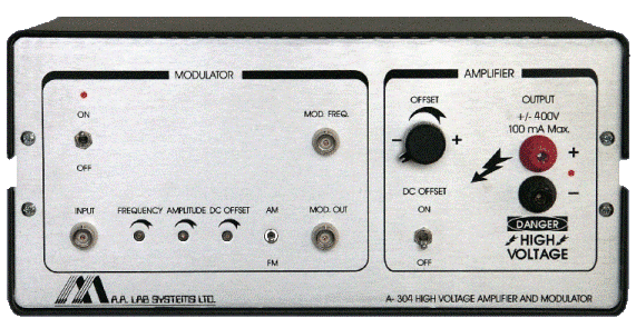
The A - 304 Piezo Driver / Piezo Amplifier is a High Voltage, High Speed Piezo Driver / Linear Amplifier combined with a Wideband AM/FM Modulator. It was especially designed as a Linear Amplifier / Driver for PIEZO Electric Actuators (also known as “Piezo Amplifier”), Stacks, Piezo Sheets, Bimorph elements and other devices. It may be also used as a general purpose High Voltage Amplifier for Medical Applications (e.g., as Electrode Driver for Neurology).
The Piezo Driver / Piezo Amplifier is based on a High Voltage, High Frequency and High Current MOSFET Amplifier which is capable of driving upto ±400V (800Vptp) at ±100mA at Frequencies from DC to 250kHz.
By connecting 2 Amplifiers in Parallel or in Series, the Output Voltage and Current may be doubled to 1600Vptp @ 100mA or 800Vptp @ 200mA. The Amplifier Section is Very Stable and has a Low Noise Output and a Very Low Electrical Noise - Compare Our Specifications!

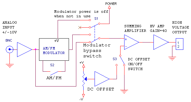
The built-in modulator (AM or FM) enables the user to modulate the carrier frequency (adjusted on the front panel) by any input signal at the range of ±10V. This modulator can be bypassed by a switch.
This High Slew Rate Amplifier / Driver can be used for various applications requesting High Slew Rate, High Voltage and Fast Response as: Plasma Driver and Plasma Actuation, Driver for Piezo Manipulator, Optical Switching Devices, Closed Loop Feedback Systems, Vibration Control, Structural Damping Analysis, Flow Actuation and Control etc.
- Features:
- Very Low Electrical Noise
- Low Distortion
- No Audible Noise: You may hear your experiment
- High Slew Rate: upto 300V/µSec
- Input Protection: High Voltage, On/Off
- Output Protection: Short-circuit, Power Loss, Impedance
- Built in Modulator:
- Amplitude(AM) or Frequency(FM) Modulation
- High Frequency: upto 100kHz
- Low Distortion
- Adjustable Frequency, Gain, Offset
- The Modulator may be turned off if not in use (only amplifier section would work)
|

|

Sync Output provides a Square Wave in the same Phase and Frequency of the Modulator Output (for synchronization and frequency measurement) |
The unit is self-cooled - no fan or noisy parts |
Amplifier Section |
Maximum Input Voltage: |
±12V |
Maximum Output Voltage: |
±400V (800Vptp) |
Maximum Current: |
±100mA |
Bandwidth: |
Into 1KΩ Resistive Load:
DC to 300kHz (-3dB)
Into Capacitive Load:
DC to 120kHz (-3dB) (1nF)
DC to 12kHz (-3dB) (10nF)
DC to 1kHz (-3dB) (0.1µF)
DC to 100Hz (-3dB) (1µF)
DC to 10Hz (-3dB) (10µF) |
Output Power: |
40 Watt Max. |
DC Gain: |
40 (upto 100 optional) |
Coupling: |
Input & Output: Direct DC Coupling |
DC Offset: |
Adjustable to ±320V + DC On/Off |
Input Impedance: |
10KΩ |
Slew Rate: |
300V/µSec |
Output Impedance: |
100Ω |
Output Noise:
(input shorted, 300kHz Bandwidth) |
10mV PTP max. (2mV RMS max.) |
Variable Gain Option: |
0 - 40X or 0 - 100X available
Consult the factory regarding that option |
Modulator Section |
Center Frequency: |
1 - 100kHz adjustable |
Modulation: |
Amplitude (AM) or Frequency (FM) |
Waveform: |
Sine Wave |
Distortion: |
0.5% Max. |
Modulation Input F.S.: |
±10V |
Modulation Input Impedance: |
10KΩ |
Sync Output: |
1Vptp, AC Coupled, 1KΩ Impedance |
Amplitude Adjustment: |
0.5Vptp to 20Vptp |
Offset Adjustment: |
±5V or 0V Fixed |
Modulator output Impedance: |
100Ω |
|
The Modulator may be turned off when not in use! |
AC Input |
Line Input Voltage: |
110/120V, 60Hz or 220/230V, 50Hz |
Line Input Current: |
1.3 A peak |
- Applications:
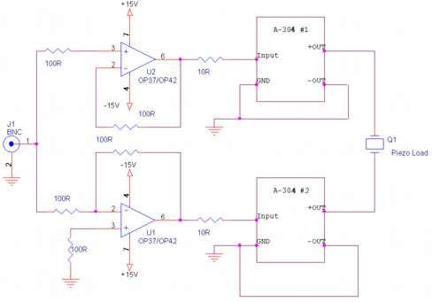
2 Amplifiers can be connected in Series or in Parallel in order to double the Output Voltage or Output Current. Series Connection (±800V into a floating load = 1600V ptp).

Please note that both amplifiers must be floating (i.e. be careful not to ground them via an oscilloscope etc.) It is also possible to double or triple the output voltage by using a special transformer. Using a transformer is possible only at high frequency (over 10kHz) and it requires more components to be added for balancing and proper termination of the load. Parallel connection is done by adding resistors at the input and at the output. Please consult the factory for parallel connection.
Calculating the estimated current needed to drive your load:
In order to purchase the right amplifier to drive your load, you must calculate the peak current needed.
For Capacitive Load:
Ipeak(A) = 2 π F C Vpeak (for a Sine Wave)
Ipeak(A) = 4 F C Vpeak (for a triangular wave)
Ipeak(A) = C dV / dt (for a square wave or sharp rise time)
F = Maximum frequency (Hz.)
C = Capacitance in Farads
Vpeak = Maximum Voltage you need to drive your Load.
π = 3.1415927
For Resistive Load:
I = Vpeak / R
Where R is the resistance of your load in ohms
The Current, Voltage and Frequency must be less or equal to the amplifier’s specifications.
This Amplifier is NOT SUITABLE for driving pure Inductive Loads
(i.e. speakers, solenoides, electromagnets etc.)
You must connect your load with thick wires to minimize inductance (like speaker wires). Coaxial cable is not recommended for cables over 2m (6.5 Ft.) because the capacitance of the cable (15-50 pF/Ft) will load your amplifier at high frequencies.
Example: |
The active impedance of a capacitive load is given by the equation: Z = 1 / (2 * π * F * C)
Where π = 3.1415, C in Farads, F in Hz.
The user must check that under the peak operation voltage, at maximum frequency, the current will not exceed 200mA (0.2A) |
Example: |
Operating Voltage is ±150V, Maximum Frequency = 10kHz, Load is 10nF
Z = 1 / (2 * 3.1415 * 10,000 * 10 * 10-9) = 1592Ω (Ohms)
150[V] / 1592[Ω] = 94[mA]
The amplifier will drive that load at an amplitude of 150V (300Vptp) |
- Frequency Response Curve for Various Loads:
All Specifications are subject to change without a Prior Notice
For any sort of clarifications kindly contact:
info@globesolutionz.com
|